
The badge
This year's badge is electronic, and a badge competition ran throughout both days.
The game is over. The badge is yours.
Unlock it and it becomes a normal ESP32-S3 board that takes any firmware you write. Unlocking erases everything on it, so read the steps before you start.
Once again, the amazing kripthor developed the conference badge, and you didn't need much to join the competition.
A USB-C cable and a powerbank were essential, and a phone or a laptop gave you the full experience.
The badge is sponsored by:

Inside the badge
An ESP32-S3 with a LoRa radio, a small screen and a handful of sensors, on a triangular board. The schematic and the PCB files, with the full bill of materials, are below.
- ESP32-S3-WROOM-1 module (N16R8: 16 MB flash, 8 MB PSRAM), with Wi-Fi and Bluetooth LE
- LoRa radio: an Ai-Thinker Ra-01SC module with a 433 MHz spring antenna
- 0.96" OLED display (I²C)
- Sensors: VEML6040 colour, AGS10 gas (VOC), SPA06-003 pressure and temperature, LSM6DS3TR-C accelerometer and gyroscope, an MSM261DHT006 MEMS microphone and an IR receiver
- Two WS2812B RGB LEDs, two buttons and four touch pads
- USB-C, a serial header (TX, RX, 3V3, GND) and a four-pin IO breakout (IO39 to IO42)
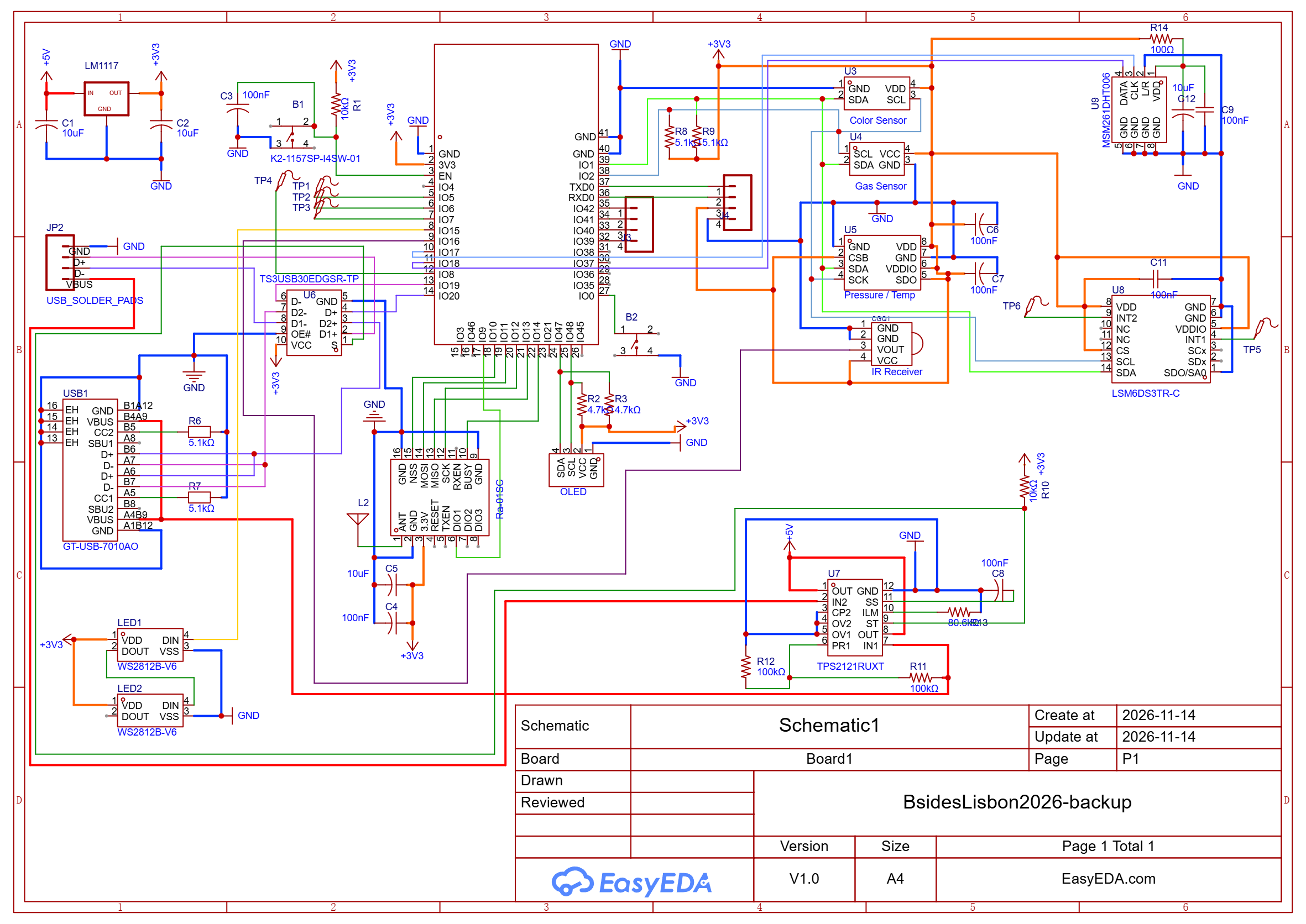
Schematic · PNG PCB & BOM · PDF
The PDF has the assembly drawings, the bill of materials (with the LCSC part numbers), the silkscreen of both sides and the drill drawing.
Demo code
A starting point for your own firmware: an Arduino sketch with a small menu and one page per part of the badge (the touch pads and button, the LEDs, the screen, the colour, gas, pressure and motion sensors, the microphone, the IR receiver and the LoRa radio), each showing everything that part can tell you. No game and no network, and the radio only listens. The board settings, the libraries it needs and the pin map are in the comment at the top.
Unlock your badge before you flash it, and flash it as the unlock page explains.